Understanding schematics.
Many guitar wiring diagrams are drawn in hard wiring form whilst some are in schematic form.
The difference is that schematics show how a circuit works whilst the others just show the layout of the components.
So, this is for people who want to be able to read schematics and know how things work. Remember that knowledge is power! Also, I hope to be able to show that by keeping effects units to a minimum your guitar will retain it's "Sparkle" in the tone.
These subjects can be as complex as you want so I have avoided going into the mathematics of it all in the hope that a simple overview will assist in people's general understanding of basic principals.
Please note that this article is for educational purposes only. Only qualified personnel should carry out any electrical work. I accept no responsibility for loss or damage, consequential or otherwise, caused through the use of information contained in this article. Nor do I encourage non qualified persons to modify or repair electrical equipment of any kind. Electricity can kill, pass any electrical work requirements to a qualified person.
Basic principles.
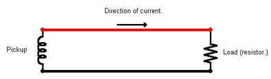
The circuit below shows a guitar pickup connected to a resistor. This is the simplest form of generating electricity and then using it up, the pickup is the generator and the resistor the "load". A "load" is something, which draws current from an electrical source. This simply means that the pickup generates an electrical current, which travels along the two wires and goes into the resistor and becomes heat. The current is so small and the heat generated so tiny that it could only be measured with special equipment but it is there!
In our circuit there is a red and a black wire connecting the two items. We normally show the earth (or ground,) wire at the bottom and the wire which carries the signal at the top - in this case in red.
It is also good practice to draw schematics showing the signal path going from left to right. In this example the signal starts life in the pickup and is used up in the resistor.
If it's resistance is too low the resistor will try to draw more current than the pickup can give and performance will suffer. A small resistance will "dampen" the coil's performance and the high frequencies will be the first to go. (A low resistance is the same as a high load.)
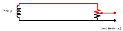
In the above circuit I have replaced the load resistor with a potentiometer (pot.). The slider can travel the length of the resistor and tap off however much of the signal is required. The signal path is shown in red and we now have the simplest guitar circuit with a pickup and a volume control. As the slider approaches earth (ground,) it will tap off fewer signals than if it is at the "hot" end.
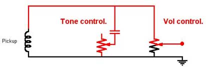
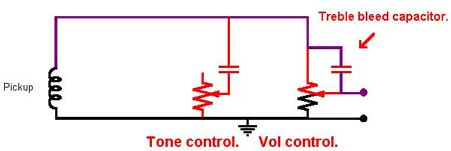
In this circuit I have added a tone control, the symbol with double lines is a capacitor which will show less resistance to high frequencies than low ones. It is drawn in red because a signal always travels through the capacitor through the variable resistor down to ground where it is lost. If the slider of the pot is at the top of the resistor the high notes have got to travel through the whole of the track to get to ground. As we move the slider towards the bottom of the track there is less resistance to the high notes and more of them are lost to ground. When the tone pot is turned fully anticlockwise the slider is touching ground and the resistor is out of circuit. Clockwise is the full resistance in circuit. The full resistance is normally calculated to drain a negligible amount of highs.
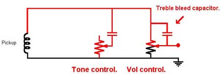
Here is the same circuit with the addition of a bleed capacitor. Capacitors will allow treble through easier than bass. A small capacitor will only allow high treble through. The above circuit allows high treble notes to bi pass the vol. control, so that if the vol. control is not fully up some extra high treble will get through, this is the circuit used in Telecasters to give that snappy sound.
The purple line shows the path, which the high treble signals travel from the pickup up through the bleed capacitor. If the tone control were turned down then the high trebles would be lost before they got to the vol. control. The bleed capacitor is only effective if the tone control is fully clockwise (max track in circuit.)
Telecaster circuit.
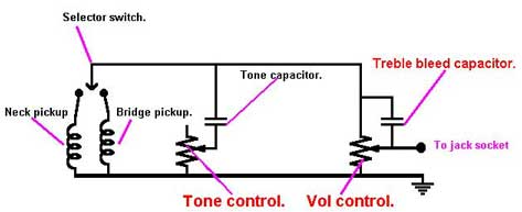
This is the final standard circuit as used in Telecaster type guitars. The selector switch can select either or both pickups. If you own a Tele try turning the vol. down, you will notice that the more you turn it, the thinner (more trebly,) the sound gets before it vanishes.
Impedance and why it matters.
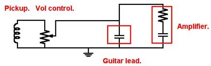
This is the equivalent circuit of a single pickup guitar connected via a guitar lead to an amplifier. This is what the guitar pickup actually "sees". The connecting lead is a capacitor, which quite effectively causes some treble to be lost to the ground, and I have represented the amplifier input by a combination of a resistor and a capacitor. Actually the resistor shown represents the "impedance". The input impedance is the resistance presented to an AC signal, the higher the input impedance an amplifier has the better the treble response.
A poor quality guitar lead will be a larger capacitor than a decent one and will suck to ground all the lovely harmonics and presence from your Super Deluxe Signature Axe which cost you the price of a family saloon car. The amplifier impedance for guitar input is different than for a mike and different again for a Hi Fi amp. This is why only a guitar amp will do justice to your guitar, the better the amp the better the design of the input. Plug in and listen.
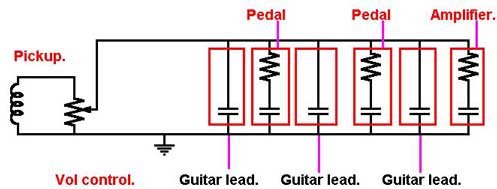
The above circuit is what your pickup would "See" if it was connected to via a vol. control through two pedals to an amp. Each pedal has it's own input impedance and each connecting cable acts as a capacitor. So before your soul-searching lead break has reached the amplifier it has had to struggle past three capacitors and though two effects pedals.
Now, a good quality effects unit has what is known as a buffer at it's input. What this does is to make sure that the input impedance is as high as possible to minimise loss. So, if you want to keep that "Sparkle" in your guitar tone, buy the best leads and the finest effects units available - you get what you pay for.
Finally.....
Whenever a signal is processed there is always loss, usually of the high frequencies. A digital effects unit has to convert the signal to digital, process it and convert it back before feeding it down the next cable. Three effects units in a row will mean that the signal has been converted to digital and back six times before reaching your amp. There is really no point paying out for a deluxe guitar if the cables and effects units throw away half of it's tone. A quality guitar is worth quality amplification.
Have fun.
Will Halligan.
Will has worked for 30 yrs. as an engineer in industry, the music trade and the recording industry. His passions are guitars (playing and repairing,) and his old Quad Hi Fi. He has worked with numerous recording artistes - squeezing the best out of whatever set up they want to use. Contact at will@post.com or via his web site at
Fender, Squier, Stratocaster, Strat, Telecaster, and Tele are trademarks of Fender Musical Instruments Corporation. I am not associated with that company. All drawings and explanations are my interpretations only and are for education and interest purposes only.